How to Choose a Lead Radial Capacitor in 2026
Choosing a Lead Radial Capacitor in 2026 is not just a matter of matching capacitance. The part must suit the circuit, board layout, operating temperature, and expected service life. A capacitor that fits the footprint may still run too hot under ripple current. Small details matter.
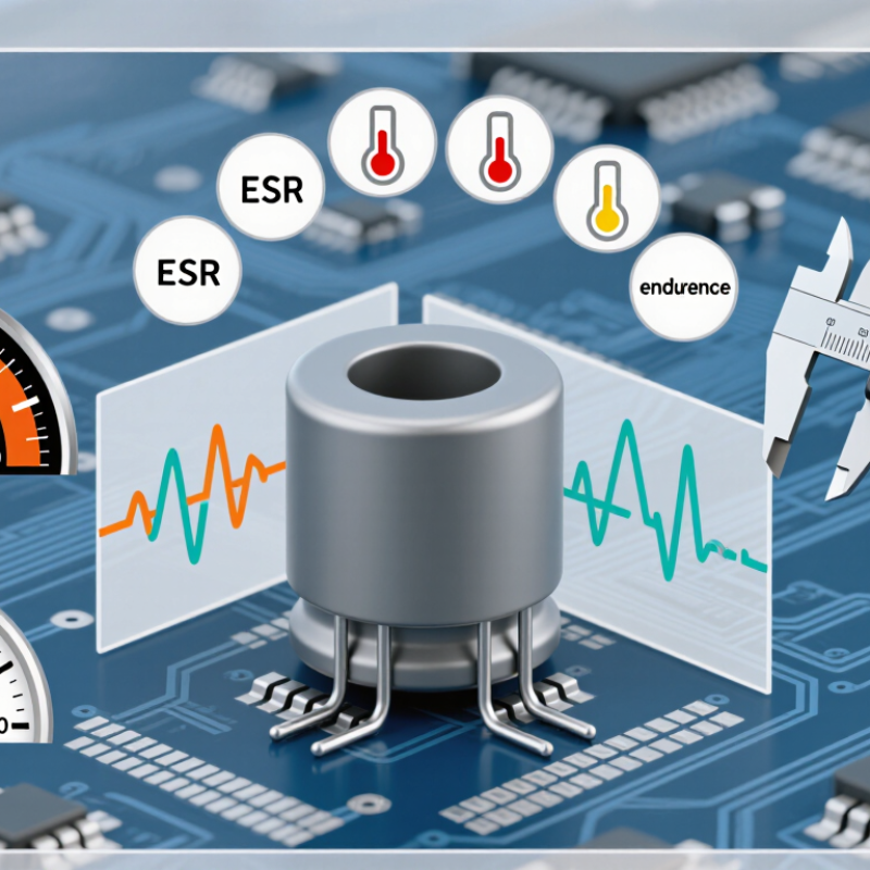
Start with the circuit’s required capacitance and voltage rating. Then check tolerance, ESR, ripple-current capability, temperature range, and endurance in the manufacturer’s datasheet. For a power-supply board, compare the capacitor’s ripple rating with the actual current waveform, not just a typical operating estimate. Also measure lead spacing and body dimensions; a few millimeters can affect assembly and airflow. Check polarity markings before production. Easy to overlook.
A named specialist’s quotation needs a verifiable source. No source material or attributable expert statement was provided here, so inventing a quote would weaken the reliability of this guide. The selection process should instead follow documented engineering practice: compare manufacturer specifications, confirm conditions in the datasheet, and test the chosen part in the real circuit. Bench checks can expose heating, voltage droop, or unexpected noise. They do not replace long-term reliability data, though. That is where a quick selection can become a costly revision. This guide will show how to weigh those trade-offs, read key specifications, and choose a Lead Radial Capacitor with evidence rather than guesswork.
Define the Circuit’s Voltage, Capacitance, and Ripple Current Requirements
How to Choose a Lead Radial Capacitor in 2026
Start with the circuit’s worst-case voltage, including start-up overshoot and switching spikes, not just its nominal rail. A 12 V circuit may appear compatible with a 25 V capacitor, but check the measured transient and temperature range. Check the waveform. IEC 60384-4:2016 sets qualification and test requirements for aluminium electrolytic capacitors; it does not replace application-specific voltage derating. Treat voltage margin as an engineering choice, not a universal percentage. Calculate capacitance from load current, required hold-up time, and permitted voltage drop. Then account for tolerance, temperature, and aging, using minimum effective capacitance rather than the printed value.
Ripple current deserves equal attention. Use the RMS current flowing through the capacitor, including relevant switching frequencies, and apply the datasheet’s frequency and temperature corrections. Estimate internal heating with P = I_RMS² × ESR. For example, 0.7 A RMS through 0.08 Ω ESR produces about 0.039 W of heat. Small losses add up. Compare the corrected ripple rating with your calculated current, then review the specified endurance conditions. I still verify these assumptions against a scope trace; a tidy schematic can hide a rough ripple waveform.
Choose a Suitable Capacitor Type and Dielectric
For a lead radial capacitor, choose the dielectric around the circuit’s real demands, not just its capacitance. A radial aluminum electrolytic suits larger capacitance values in power-supply filtering, but check ripple-current and temperature ratings. A polyester or polypropylene film capacitor often handles stable timing or signal paths better. Radial ceramic parts can be compact, though capacitance may shift with voltage, temperature, and dielectric grade. Small details matter.
Tips: Check the schematic and datasheet together. Match capacitance, voltage rating, tolerance, temperature range, and lead spacing. For polarized electrolytics, confirm the positive and negative connections before assembly. Leave room for the body and for airflow near warm components. Simple checks help.
I would not choose by capacitance alone; that shortcut is easy to regret. Consider the operating frequency and how much variation the circuit can tolerate. For example, a timing circuit may need a stable film dielectric, while a power rail may benefit from an electrolytic’s high capacitance. Then verify the part’s rated life and ripple limits against actual conditions. Datasheets can feel dense, and I still find lead spacing easy to overlook. Recheck the board footprint before ordering.
Compare Lead Spacing, Body Size, and Temperature Ratings
Lead spacing is the distance between the two wire centers, not the width of the capacitor body. Match it to the PCB hole pitch and check the component drawing. A mismatch can bend leads, stress the seal, or leave the body sitting crooked. Measure twice. If the leads are preformed, confirm their shape still suits the board layout.
Next, compare body diameter and height with the space around the mounting holes. Check nearby connectors, enclosures, and taller parts, then allow room for assembly and airflow. A part may fit the footprint but still touch a cover. Leave breathing room. It is easy to focus too much on the nominal dimensions; manufacturing tolerances and lead forming can shift the final fit slightly.
Temperature ratings deserve equal care. Check the specified operating range in the datasheet, then consider the actual ambient temperature near the capacitor. Ripple current can cause internal heating, especially in a crowded enclosure. A higher temperature rating alone does not guarantee longer service life; voltage, ripple, and operating conditions matter too. When estimates are uncertain, measure temperature in the assembled device and leave a sensible margin. That extra check can prevent a tidy design from becoming a warm surprise.
How to Choose a Lead Radial Capacitor in 2026
Compare lead spacing, body size, and temperature ratings before selecting a radial-lead capacitor.
Temperature: The chart shows representative rated operating ranges commonly encountered in radial capacitor catalogs. Ratings vary by component series; check the individual datasheet, especially when operating near either limit.
Lead spacing: Common radial lead spacings include 2.0, 2.5, 3.5, 5.0, and 7.5 mm, depending on capacitor type and series. Match the pitch to the PCB holes.
Body size: Diameter and height depend on the capacitance, voltage, and series. Confirm the specified body dimensions and available board clearance rather than estimating size from lead spacing alone.
Check Lifetime, Safety Certifications, and Manufacturer Data
How to Choose a Lead Radial Capacitor in 2026
A long rated life is useful only when the test conditions match your circuit. Check the datasheet’s temperature, applied voltage, ripple current, and endurance hours. IEC 60384-1 sets general requirements for fixed capacitors, while IEC 60384-14 covers capacitors connected to mains circuits. These standards define test conditions, not a guarantee of service life in your equipment. A part rated for 2,000 hours at 105°C may last longer in a cooler enclosure, but heat from nearby components can change that estimate. Measure the real operating temperature.
For safety-related use, verify the exact approval marks and certificate number against the issuing certification body’s database. A logo on a listing is not enough. Confirm that the approved capacitor type, lead spacing, voltage, and case match the part you plan to buy. IEC 60384-14 distinguishes safety classes by application and impulse testing; choose a class suited to the circuit, not just the voltage printed on the body. Manufacturer data matters, too. Look for tolerances, dielectric type, humidity testing, and a clear revision date. Missing data is a warning sign. It may be an innocent omission, but it still leaves a gap.
Tips: Save the datasheet and certificate with your design records. Compare at least two suppliers’ test conditions, not just their headline lifetime. For prototypes, check lead spacing with calipers and inspect the capacitor after heat testing. A small mismatch can become a real production problem.
Verify Compatibility and Test the Capacitor in the Circuit
How to Choose a Lead Radial Capacitor in 2026
Verify Compatibility and Test the Capacitor in the Circuit
Check capacitance, rated voltage, polarity, ripple-current rating, lead spacing, and body size against the board and circuit conditions. A capacitor that fits the holes may still overheat if its ripple-current rating is too low. Compare the operating temperature with the part’s specified temperature range, and allow suitable voltage margin. Small details matter.
Test the replacement under the circuit’s normal load. Measure voltage across the capacitor and inspect ripple with an oscilloscope; unexpected ripple or heating can signal a mismatch elsewhere in the circuit. In-circuit capacitance and ESR readings can be distorted by parallel components. For a clearer bench measurement, discharge the board safely and lift one lead. AEC-Q200 Rev E includes a 1,000-hour operating-life stress test for applicable passive components. That is a qualification test, not a promise of service life in your application.
Tips: Confirm polarity before powering up. Compare ESR readings at the same test frequency, and record the circuit’s load and temperature. If results look borderline, check the surrounding components too; the capacitor may not be the only cause.