Pressure Reducing
Pressure Sustaining / Pressure Relief
Flow Control valves
Float Valves - Level Control
Electrically Actuated Valves
Pressure Modulation - Remote Control
Altitude Valves - Level Control
Burst Control Valves
Pump Control
CLA-VAL "HYTROL" Main Valve
Valve Controllers and Data Loggers
Air Valves
Choosing the right Injection Molding Equipment can affect part quality, production costs, and delivery schedules. A machine that looks suitable on paper may struggle with a specific resin, mold, or target cycle time. The key is to match equipment capabilities to real production needs, not just a headline specification. Small details matter. Shot size, clamping force, screw design, and temperature control all influence how reliably a machine fills and forms a part.
On a shop floor, a mismatch can show up as uneven filling, excessive flash, or long cooling times. These problems may lead to scrap, extra adjustments, and missed deadlines. Buyers should compare the expected part dimensions and material with the machine’s operating range, then consider mold compatibility, automation, maintenance access, and available technical support. Energy use and floor space also deserve attention, especially when production volumes may change. It is easy to focus on purchase price alone. That is not always the right first move. A lower initial cost may not reflect the expense of downtime or difficult changeovers. Still, estimates depend on actual process conditions, so no single machine specification guarantees a good result. Careful evaluation, clear supplier questions, and a realistic production trial can help reveal what works—and what needs reconsideration.
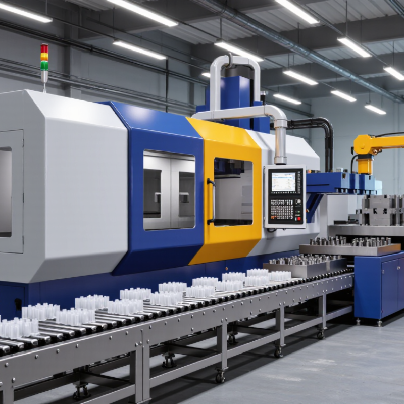
Injection molding equipment converts polymer pellets into finished parts through heat, pressure, and controlled cooling. A dryer reduces moisture before pellets enter the heated barrel. Inside, a rotating screw melts and mixes the material, then pushes a measured shot into the mold. The clamping unit holds the mold closed against injection pressure. After cooling, the mold opens and the part is ejected. That sequence repeats.
The equipment includes more than the molding press. Molds shape the part, temperature controllers regulate cooling channels, and robots or conveyors can move finished pieces. Each element affects cycle time and consistency. For example, uneven cooling around a thick rib can cause warping or sink marks. Operators monitor temperatures, pressure, and cycle records to catch changes before defects spread. Small details matter.
A suitable machine must match the part’s size, material, and required output. Excessive clamping force can waste energy, while insufficient force may allow material to escape at the mold seam. Still, a capable machine cannot compensate for every problem. Mold wear, a drifting sensor, or an outdated setup sheet can disrupt production. Real processes are not perfectly tidy; careful checks help teams understand what the equipment is actually doing.
Why Choose the Right Injection Molding Equipment?
How Product Requirements Shape Equipment Selection
A product’s geometry, resin, and production volume should guide equipment selection. A thin-walled enclosure may need fast, consistent filling. A thick component may require longer cooling and careful control of shrinkage. Machine capacity matters, but larger is not automatically better. Match shot size and clamping force to the mold and part, with room for process variation.
Material choice changes the decision, too. Some resins need higher melt temperatures or more drying control. Delicate details may call for precise injection speed and pressure. For a family mold, uneven cavity filling can complicate an otherwise simple setup. Check the mold layout, expected cycle time, and quality tolerances before comparing machines. A spreadsheet helps, but it can miss an awkward setup or difficult changeover. That happens.
Tips: Bring a sample part, resin data, and target output to the equipment review. Ask how settings will be verified during a trial. Leave a little capacity for real-world variation, not unlimited headroom. Small details count.
Why Choose the Right Injection Molding Equipment?
Which Machine Features Affect Production Performance
Machine selection affects more than cycle time. It shapes part consistency, energy use, and how quickly operators can respond to variation. Clamping force is one key factor: too little can let the mold separate and cause flash. Excessive force may add wear without improving the part. Match the machine’s rated force to projected area, material, and mold design, then verify the setup with trials. Small details matter.
Injection unit capacity matters too. The shot size should suit the part and runner volume without pushing the screw to its limits on every cycle. Screw design, injection pressure, and speed influence how resin melts and fills thin ribs or deep sections. A stable cushion can help reduce variation between shots. But a larger unit is not automatically better; poor sizing can increase residence time and complicate processing for heat-sensitive materials.
Controls and auxiliary equipment also affect output. Consistent temperature control, pressure monitoring, and clear alarm records help teams identify process drift before rejects accumulate. Check cooling capacity, dryer performance, and robot access alongside the press. Awkward part removal can erase the benefit of a faster theoretical cycle. Specs can mislead. Compare trial data across shifts, not only best-case figures. It is easy to overlook how much routine handling affects real production.
| Machine feature | Useful measurement | Example data or calculation | Production performance effect | What to check when selecting |
|---|---|---|---|---|
| Clamping force | kN or tonnes; compare with projected part area and cavity pressure. | Illustrative calculation: 10,000 mm² projected area × 40 N/mm² cavity pressure = 400 kN, before any design margin. | Adequate force helps keep the mold closed during filling and packing, reducing the risk of flash. Excessive force can add unnecessary load to the mold and machine. | Size against the total projected area of all cavities and runners, expected cavity pressure, and the mold supplier’s recommendations. |
| Injection rate and pressure | Injection rate in cm³/s; maximum injection pressure in MPa. | At an average rate of 50 cm³/s, delivering 100 cm³ takes 2 seconds (100 ÷ 50), before accounting for the actual fill profile. | Available rate and pressure affect filling time and the ability to fill thin sections or long flow paths. The required settings depend on the resin, part, and mold. | Compare the machine’s injection performance with the mold’s required fill profile and the material’s processing requirements. |
| Shot capacity and shot-size match | Maximum shot mass in g or kg; actual shot mass per cycle. | Check the complete shot: parts plus runner, where applicable. Convert between volume and mass using the resin’s density at the relevant conditions. | A suitable shot capacity supports consistent metering and avoids choosing a barrel that is poorly matched to the job. | Confirm the usable shot range for the specific screw and material with the machine supplier; do not rely on maximum shot size alone. |
| Plasticizing capacity and recovery time | Plasticizing capacity in kg/h; screw recovery time in seconds. | For a 0.05 kg shot and a 15-second cycle: 4 cycles/min × 60 = 240 shots/h; 240 × 0.05 kg = 12 kg/h of material demand. | If the screw cannot prepare the next shot within the available cycle time, recovery can become the cycle-time bottleneck. | Verify capacity using the intended resin and processing conditions, and compare recovery time with the time available before the next injection. |
| Clamp opening, daylight, and tie-bar spacing | Opening stroke and daylight in mm; tie-bar spacing and platen dimensions in mm. | Compare the mold’s outside dimensions and height with the machine’s available mounting area, daylight, and opening stroke. | Adequate clearance enables mold installation, part release, and robot access without restricting the intended mold design. | Check mold width, height, weight, thickness, opening requirements, and any gripper or ejector clearance. |
| Control of injection and packing | Repeatability of injection speed, pressure, position, cushion, and switchover settings. | Record these process values across repeated cycles and compare them with the validated process window for the part. | Stable control helps maintain consistent filling and packing, supporting repeatable part weight and dimensions. | Review machine specifications and trial data; confirm that the required control functions and monitoring are available. |
| Cycle-time capability | Seconds per cycle, including injection, packing, cooling, mold movement, and ejection. | Illustrative cycle: 2 s filling + 10 s cooling + 3 s mold movement and ejection = 15 s total. | The longest necessary stage can limit output. Cooling requirements are often strongly influenced by part geometry, resin, and mold cooling design. | Use a production trial to measure each stage; distinguish machine limits from mold, material, and part-design constraints. |
| Energy consumption | kWh per production run or kWh/kg of acceptable output. | Calculate kWh/kg by dividing measured machine energy use (kWh) by the mass (kg) of acceptable parts produced over the same period. | Energy use contributes to operating cost. Actual consumption varies with the machine, process settings, resin, cycle, and auxiliary equipment. | Compare measured consumption under equivalent production conditions, including heaters, dryers, pumps, and other relevant auxiliaries. |
Note: Numerical examples are illustrative calculations, not universal machine-sizing recommendations. Confirm requirements using the part, mold, resin, and machine specifications.
Why Choose the Right Injection Molding Equipment?
How Equipment Choice Influences Quality and Cost
Equipment affects part consistency, cycle time, scrap, and energy use. A press with suitable clamping force and shot capacity can help prevent flash, short shots, and unnecessary material waste. Stable temperature control matters too: small shifts can change how a part fills and cools. The U.S. Department of Energy’s 2002 Industrial Electric Motor Systems Market Opportunities Assessment estimated that motor systems used 68% of manufacturing electricity. This is an old, broad estimate, not an injection-molding benchmark. Still, it highlights why drive efficiency deserves attention when comparing operating costs.
Tips: Match the machine to the part and mold, not just the largest planned order. Check shot size, clamp force, control repeatability, and energy use under realistic cycle conditions. Ask for trial-run data. A low purchase price can hide higher scrap or energy costs.
Scale matters. PlasticsEurope’s Plastics—The Fast Facts 2023 reported 400.3 million tonnes of global plastics production in 2022. That figure does not measure molding-machine performance, but it shows the size of the material stream where processing losses add up. Compare suppliers using the same resin, mold, and cycle settings. Record good-part rate and energy per part. One limitation: a short trial may not reveal maintenance needs or seasonal variation, so cost estimates still need checking after production begins.
Why Choose the Right Injection Molding Equipment?
How to Match a Machine to Production Needs
Match the machine to the part, mold, material, and expected production rate. Start with real job data, not a best-case estimate. Record part weight, projected area, resin type, target cycle time, and annual volume. These details help narrow the required shot capacity and clamping force. Leave room for normal variation, such as material changes or a heavier runner.
Check that the mold fits between the tie bars and within the machine’s platen dimensions. Then review injection pressure, screw size, and available automation. A large machine may seem safer, but it can raise energy use and make small shots harder to control. A smaller press may struggle with a wide mold or demanding cycle. There is no perfect spreadsheet for every job. Recheck assumptions against actual trials; estimates can be wrong.
Tips: Ask suppliers to verify shot size and clamp force using your part and mold data. Compare expected cycle times with measured results, and keep a little capacity for future changes.
Match clamping capacity to the projected area of the molded part.
Estimates use a cavity pressure of 30 MPa: required clamp force (kN) = projected area (cm²) × 3. This is a screening estimate; confirm the required machine capacity with the mold design, material, part geometry, and process conditions.
CLA-VAL UK Limited
Dainton House
Goods Station Road
Tunbridge Wells
Kent, TN1 2DR
© 2025 CLA-VAL UK | site map | Terms and Conditions of Sale and Warranty | Privacy policy