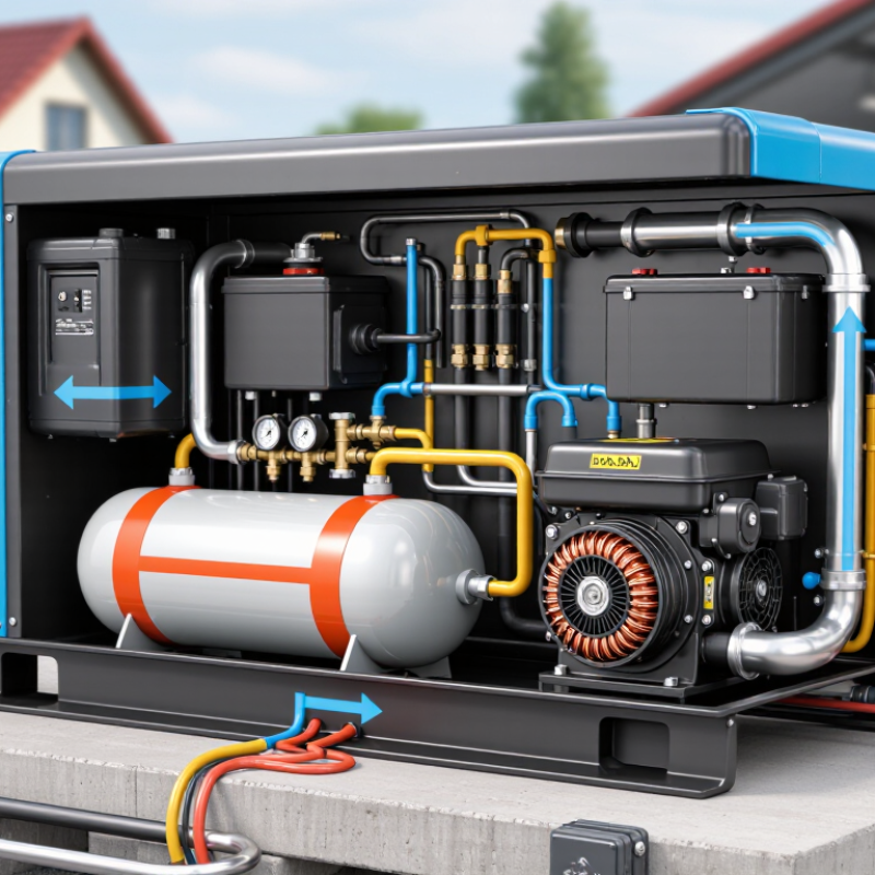
| 1 | LPG Storage Tank | Liquefied petroleum gas is stored under pressure in a suitable cylinder or bulk tank. LPG remains liquid inside the tank but produces vapor when pressure is reduced. | Main fuels: propane, butane, or a mixture of both. LPG has a typical lower heating value of approximately 46–50 MJ/kg. | A controlled fuel source is available for the engine. |
| 2 | Fuel Shutoff and Safety Valve | The fuel line passes through manual and/or automatic shutoff devices. These valves stop fuel flow during shutdown, low oil pressure, overspeed, or other fault conditions. | Safety systems are designed to isolate the fuel supply during abnormal operating conditions. | Fuel delivery can be stopped quickly to reduce fire and engine risks. |
| 3 | Vaporizer or Pressure Regulator | The regulator reduces tank pressure to the low pressure required by the fuel system. If liquid LPG must be converted to vapor, heat from the surroundings or engine coolant may assist vaporization. | Fuel pressure varies by appliance and generator design; the regulator must match the engine fuel system and local LPG specification. | Stable gaseous fuel pressure is supplied to the mixer or injection system. |
| 4 | Air-Fuel Mixer or Gas Injection System | LPG vapor is mixed with intake air before entering the cylinders. Some engines use a venturi mixer, while others use electronically controlled gas injection. | For propane, the chemically balanced air-fuel ratio is approximately 15.7:1 by mass. Actual operation uses a controlled mixture that may vary with load. | A combustible air-fuel mixture reaches the engine cylinders. |
| 5 | Air Intake and Throttle Control | The throttle regulates the amount of air-fuel mixture entering the engine. The governor or electronic controller adjusts engine output as electrical demand changes. | Increasing electrical load requires more fuel and air to maintain engine speed and generator frequency. | The engine receives the quantity of mixture needed for the connected load. |
| 6 | Engine Compression | In a typical four-stroke spark-ignition engine, the piston compresses the air-fuel mixture inside the cylinder as it moves upward. | A four-stroke cycle consists of intake, compression, power, and exhaust strokes. | The mixture is prepared for ignition at a higher pressure and temperature. |
| 7 | Spark Ignition | The ignition system produces a spark at the spark plug. The spark ignites the compressed LPG-air mixture. | LPG generators normally use spark-ignition engines rather than compression-ignition diesel engines. | Rapid combustion begins inside the cylinder. |
| 8 | Combustion and Piston Movement | Combustion raises cylinder pressure and forces the piston downward. The connecting rod transfers this force to the crankshaft. | The chemical energy of LPG is converted into reciprocating mechanical motion. | The crankshaft receives mechanical torque. |
| 9 | Crankshaft and Speed Regulation | The crankshaft converts piston motion into rotation. A governor maintains a nearly constant rotational speed as the electrical load changes. | Common synchronous-generator speeds are 3,000 rpm at 50 Hz or 3,600 rpm at 60 Hz for two-pole machines; four-pole machines commonly use 1,500 rpm at 50 Hz or 1,800 rpm at 60 Hz. | Stable mechanical rotation is delivered to the alternator. |
| 10 | Alternator Rotor and Stator | The engine turns the rotor inside the alternator. The rotating magnetic field induces an alternating voltage in the stator windings through electromagnetic induction. | The alternator converts mechanical energy into electrical energy. Output frequency depends mainly on rotational speed and the number of magnetic poles. | Electrical power is produced as alternating current. |
| 11 | Voltage Regulation | An automatic voltage regulator adjusts the alternator excitation to help maintain the selected output voltage as the load varies. | Common low-voltage configurations include approximately 120/240 V or 230/400 V, depending on the electrical system and configuration. | Voltage remains within the generator's specified operating range. |
| 12 | Control Panel and Protection | The control system monitors voltage, frequency, current, oil pressure, coolant temperature, and engine speed. Circuit protection disconnects the load during overloads or faults. | Protective functions may include overload, short-circuit, low oil pressure, high temperature, overspeed, and emergency shutdown. | The generator operates more safely and can be shut down automatically when necessary. |
| 13 | Power Distribution | Electricity passes through the circuit breaker, transfer equipment, or distribution panel before reaching connected appliances and electrical loads. | Generator capacity is commonly expressed in watts or kilovolt-amperes. Real power is measured in kW, while apparent power is measured in kVA. | Usable electrical power is delivered to the connected system. |
| 14 | Exhaust and Heat Management | Combustion gases leave through the exhaust system, while the cooling system removes heat from the engine. The enclosure or ventilation system helps manage noise and temperature. | Exhaust gases contain carbon dioxide, water vapor, nitrogen, and regulated pollutants such as carbon monoxide and nitrogen oxides. | Heat and combustion by-products are directed away from the engine and operating area. |
| 15 | Shutdown and Cooldown | When the generator is stopped, the fuel valve closes and the engine may continue briefly without load to dissipate heat before turning off completely. | Cooldown duration depends on engine size, operating load, ambient temperature, and the control system. | The generator stops in a controlled manner and remains ready for the next start. |