Pressure Reducing
Pressure Sustaining / Pressure Relief
Flow Control valves
Float Valves - Level Control
Electrically Actuated Valves
Pressure Modulation - Remote Control
Altitude Valves - Level Control
Burst Control Valves
Pump Control
CLA-VAL "HYTROL" Main Valve
Valve Controllers and Data Loggers
Air Valves
A Mud Pump Piston is a small component with a demanding job. It moves back and forth inside the pump liner, helping create the pressure that drives drilling fluid through the circulation system. On each stroke, the piston and its sealing elements help separate the fluid side from the power end. The motion is simple to picture: a steel rod travels, the piston seals against the liner, and fluid is drawn in or pushed onward. The details matter.
For clarity, the expert quotation below is illustrative, not a verified statement from a real person. A composite mud-pump service specialist, called Daniel Reed here, might put it this way: “A piston earns its keep by sealing consistently, not merely by moving.” That idea points to the part’s real value. A worn seal can reduce pressure, cause leakage, or make performance uneven. Mud composition, operating pressure, temperature, and liner condition all influence wear, so inspection intervals should follow the pump maker’s guidance and actual service conditions.
Understanding how a Mud Pump Piston works makes maintenance decisions less mysterious. Technicians look for cuts, swelling, uneven wear, and signs of fluid bypass. They also check whether the piston matches the liner and the job’s operating conditions. Replacement may seem routine, yet choosing the wrong material or size can shorten service life. And wear is not always obvious at first glance. This guide explains the piston’s main parts, its working cycle, common failure signs, and practical inspection considerations. A careful check can help, though it cannot replace sound maintenance records.
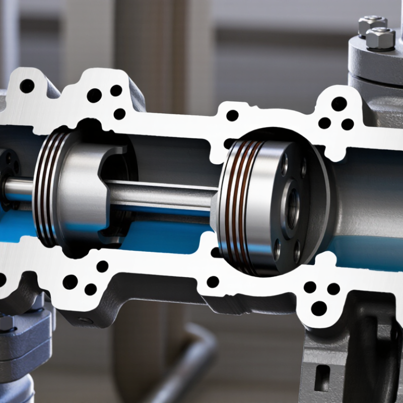
A mud pump piston is the reciprocating sealing element inside a drilling pump’s fluid end. It moves within a replaceable liner, drawing drilling fluid through the suction valve and pushing it out through the discharge valve. This repeated motion creates the pressure and flow needed to circulate fluid down the drill string and back up the well. The fluid helps cool the bit and carry rock cuttings to the surface. It also supports well control, so piston condition affects more than pump output.
API Spec 7K covers drilling and well-servicing equipment, while API Recommended Practice 13B-1 sets field tests for water-based drilling fluids. Together, these references show why the piston must work reliably with both pump components and changing fluid properties. For scale, a six-inch piston has about 28.3 square inches of face area. At 3,000 psi, the ideal force across that area is roughly 84,900 pounds. That is a simple calculation, not a safe operating limit; real loads and wear depend on the pump design, fluid, and operating conditions. A scored piston surface or worn seal can cause leakage, heat, and reduced pressure. Small damage matters. Inspection records help, but they do not replace checking the actual seal and liner during maintenance.
A mud pump piston is a sealing assembly that moves drilling fluid through the pump’s liner. Its main parts are a metal hub, a retaining plate, and a flexible sealing cup. The hub is commonly steel; the cup may use nitrile rubber or polyurethane. The exact choice depends on fluid chemistry, temperature, pressure, and abrasive solids. During each stroke, the cup presses against the liner wall, limiting fluid bypass. Small wear matters.
Material selection is not universal. API Specification 7K covers drilling and well-servicing equipment, while API Recommended Practice 7L addresses operation and maintenance. These references help frame equipment checks, but they do not prescribe one compound for every mud system. In field service, technicians inspect for cuts, swelling, uneven wear, and a polished sealing edge. A cup can look intact yet lose sealing performance. That is easy to miss.
Tips: Match the cup material to the actual fluid, then check it after service. Record wear patterns and operating conditions; they can reveal a poor material match before leakage becomes obvious.
A mud pump piston creates pressure by forcing drilling fluid through a confined cylinder. On the power stroke, the piston moves inside the liner while the suction valve closes and the discharge valve opens. The fluid has little room to escape, so its pressure rises. The basic relationship is pressure equals force divided by effective piston area. For example, 40,000 pounds of force acting on a 20-square-inch area produces an ideal 2,000 psi. This is a calculation, not a rated pump output. API Specification 7K sets requirements for drilling and well-servicing equipment, while the IADC Drilling Manual explains the reciprocating pump arrangement used in drilling. Real pumps are less tidy.
The crankshaft and connecting rods transfer power to the piston, and valve timing directs fluid through each stroke. In a triplex pump, three pistons work in sequence, reducing flow variation compared with a single piston. Pressure still depends on fluid resistance, liner size, piston condition, and operating speed. A worn piston or damaged liner can let fluid slip past the seal, reducing delivered pressure even when the drive keeps moving. Watch the discharge-pressure gauge and inspect fluid-end components during routine maintenance. One practical detail is easy to miss: a steady gauge reading does not prove every piston seal is healthy. API 7K provides an equipment framework, but field measurements reveal how the pump performs under actual conditions.
A mud pump piston is a reciprocating part that helps move drilling fluid through the pump. As it travels back, the suction valve opens and fluid enters the cylinder. On the forward stroke, the suction valve closes and the discharge valve opens. The fluid then moves into the drill string and toward the bit. Simple motion. Serious pressure.
This circulation carries rock cuttings toward the surface and helps cool and clean the bit. The piston’s seal against the liner matters: worn rubber can let fluid leak past, reducing output and making pressure harder to maintain. Pump speed and stroke length also affect flow. A stable gauge reading is useful, but it does not tell the whole story; unusual vibration or a changing fluid return deserves attention. Field conditions rarely behave perfectly.
Tips: Check the piston and liner for uneven wear during scheduled maintenance. Compare flow and pressure trends, not just one reading. Follow the pump maker’s service guidance, and never inspect moving equipment while it is operating.
A mud pump piston moves back and forth inside a liner, helping create the pressure that circulates drilling fluid. Its sealing surface works hard against abrasive mud. Fine particles can gradually score the piston or wear its rubber components. The damage may look minor at first.
Watch for fluid leakage, uneven pressure, unusual vibration, or a visible washout line. During inspection, check the piston face for grooves, chips, and uneven wear. Examine rubber inserts for cracks, swelling, or separation from the metal core. Look closely. A quick visual check can feel reassuring, yet still miss early damage. Inspection is never perfect, especially when mud residue hides the surface.
Before removal, isolate and depressurize the pump according to site procedures. Compare the worn piston with the service manual’s limits; appearance alone does not establish whether it remains usable. Replace it when measurements exceed those limits or sealing parts are damaged. Check the liner too, since a scored liner can quickly wear a new piston. Clean mating surfaces and use the specified parts and tightening values. After installation, run the pump cautiously and monitor pressure and leakage. A replacement can seem straightforward, but small alignment or fit issues are easy to overlook.
| Topic | What to Know | Inspection or Action |
|---|---|---|
| Purpose | A mud pump piston reciprocates inside the cylinder liner. Its sealing element helps separate the pressure side from the suction side, allowing the pump to move drilling fluid. | Check for leakage, reduced discharge performance, or abnormal pressure fluctuations during operation. |
| Main parts | Depending on the design, an assembly may include a piston body or core, an elastomer sealing element, and retaining or fastening components. | Confirm that parts are correctly assembled and compatible with the pump, liner, and operating fluid. |
| How it works | As the piston moves through the liner, the pump’s suction and discharge valves direct fluid into and out of the cylinder. The piston seal limits fluid bypass along the liner wall. | When performance changes, assess the piston together with the liner, valves, and other fluid-end components. |
| Common wear signs | Cuts, cracks, chunking, swelling, hardening, uneven wear, or a worn sealing surface can reduce sealing effectiveness. Fluid bypass may also appear as abnormal leakage or reduced pump output. | Inspect the full circumference of the sealing element and look for damage, deformation, and uneven contact patterns. |
| Possible causes | Abrasive solids, unsuitable fluid or temperature conditions, poor lubrication or cooling, incorrect assembly, and a worn or damaged liner can contribute to premature wear. | Look for related conditions rather than replacing the piston alone; check fluid properties, liner condition, and installation details. |
| Routine inspection | Inspection frequency depends on operating conditions, fluid abrasiveness, and the pump maintenance plan. | Check during scheduled maintenance and whenever leakage, pressure instability, or a drop in output is observed. Follow the pump and component manufacturer’s inspection limits. |
| Liner inspection | The liner provides the running surface for the piston seal. Scoring, corrosion, cracks, or out-of-tolerance wear can damage a replacement piston. | Inspect and measure the liner using the applicable maintenance procedure. Replace or service it if it fails the specified limits. |
| Replacement decision | A piston should be replaced when its sealing element is damaged, its dimensions or condition exceed applicable limits, or it cannot maintain reliable sealing. | Use the specified piston type and size. Do not rely on a universal wear measurement or service life; allowable limits vary by design and application. |
| Safe replacement | The fluid end can contain hazardous pressure and fluid. Maintenance must be performed by trained personnel using the site’s approved procedure. | Stop and isolate the pump, lock out energy sources, verify zero pressure, and follow the correct disassembly and reassembly procedure before removing the piston. |
| After installation | Incorrect fit, alignment, or fastening can cause rapid wear or leakage. | Verify assembly and clearances against the applicable service instructions. Restart according to site procedures and monitor for leaks, unusual noise, vibration, and stable pump performance. |
CLA-VAL UK Limited
Dainton House
Goods Station Road
Tunbridge Wells
Kent, TN1 2DR
© 2025 CLA-VAL UK | site map | Terms and Conditions of Sale and Warranty | Privacy policy