
What Is a VFD PCB Board and How Does It Work?

What Is a VFD PCB Board and How Does It Work?

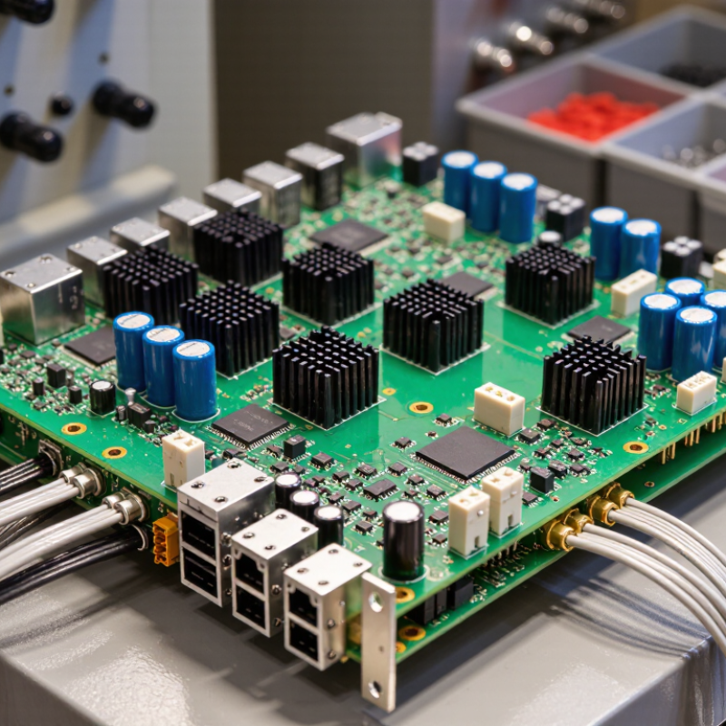
A Vfd Pcb Board is the electronic control center inside a variable frequency drive. It helps regulate motor speed, torque, and direction with carefully timed electrical signals. In practical applications, this board connects low-voltage control logic with powerful switching components. That connection must remain stable under heat, vibration, dust, and electrical noise.

A typical VFD changes incoming AC power into DC through a rectifier section. Capacitors then smooth the DC bus voltage. An inverter stage uses IGBTs or MOSFETs to create a controlled AC output. The Vfd Pcb Board sends gate-drive signals to these switches, often using pulse-width modulation. By changing output frequency and voltage, the drive adjusts motor performance for pumps, conveyors, fans, and compressors.

It also monitors current, voltage, temperature, and fault conditions. Feedback signals allow the controller to correct operation or shut down safely. This process sounds straightforward. It is not always simple.

Engineers usually inspect circuit diagrams, firmware settings, grounding methods, and thermal paths together. A damaged sensing circuit may appear harmless, yet it can cause unstable motor behavior or repeated trips. The board’s layout also matters. Short signal paths, suitable isolation, and proper shielding can reduce interference.

Reliable manufacturers validate VFD designs through thermal testing, electrical stress checks, and documented protection procedures. Qualified technicians should follow the drive manual and applicable safety requirements before testing any energized equipment. One detail deserves reflection: not every VFD PCB carries the same functions. Some boards manage control logic, while others combine power conversion and protection. Understanding that difference makes diagnosis more accurate and replacement decisions less risky.
What Is a VFD PCB Board and How Does It Work?

VFD PCB Definition: AC–DC–AC Conversion at 95–98% Efficiency

A VFD PCB board is the circuit platform that helps a variable-frequency drive convert incoming AC power into controlled AC output.

A rectifier first changes the input AC into DC. Capacitors smooth the DC bus, reducing voltage ripple. An inverter stage then switches that DC into AC at a selected frequency and voltage.

This lets a motor run at different speeds. That is the core.

The 95–98% efficiency figure usually describes a well-designed drive under suitable operating conditions, not the bare PCB alone.

Actual efficiency varies with load, switching frequency, cooling, and component condition. For example, a dusty enclosure or loose connection can raise temperatures and increase losses.

Heat still matters. Engineers check board layout, current paths, insulation spacing, and thermal behavior during design and testing.

A practical detail is the DC bus: its voltage can remain hazardous after power is removed, so service procedures must account for stored energy.

Efficiency figures are useful, but they need context.

A drive running lightly loaded may not match a peak rating, and field measurements can reveal losses that a datasheet does not show.

Power Stage Architecture: 600–1,200 V IGBTs, DC Bus, and Gate Drivers

What Is a VFD PCB Board and How Does It Work?

A VFD PCB controls motor speed by converting fixed-frequency AC into adjustable electrical output. Its power stage usually contains 600–1,200 V IGBTs, a rectifier, a DC bus, and isolated gate drivers. The rectifier creates pulsating DC. Capacitors then smooth it into a high-energy DC link. For a 400 V AC supply, the bus may approach 565 V under ideal conditions. Voltage spikes and regeneration require additional design margin.

The IGBTs switch this bus rapidly through pulse-width modulation. Gate drivers control turn-on timing, dead time, fault shutdown, and isolation. Desaturation detection can react to a short circuit within microseconds. Layout matters greatly. Short copper paths reduce stray inductance and ringing. Poor placement can damage an otherwise correctly rated transistor. The International Energy Agency reported that motor-driven systems consume about 46% of global electricity, making efficiency improvements technically significant. Still, switching losses, heat, and acoustic noise cannot disappear completely. The design is a compromise.

Tips: Check the DC-bus ripple under real load, not only at room temperature. Measure gate signals at the IGBT pins. Verify creepage and clearance for the working voltage. A clean waveform may still hide dangerous overshoot. Review protection thresholds again. Small assumptions become expensive failures.

What Is a VFD PCB Board and How Does It Work? – Power Stage Architecture: 600–1,200 V IGBTs, DC Bus, and Gate Drivers

Architecture Element Typical Specification Primary Function How It Works in a VFD Important Design Considerations
Input Rectifier Six-pulse diode or controlled rectifier bridge Converts incoming AC voltage into a pulsating DC waveform. For a three-phase supply, six rectifier devices conduct in pairs and create a DC output with six voltage pulses per line cycle. The bridge must withstand input surges, line transients, repetitive current, and thermal stress.
DC Bus Capacitors Electrolytic capacitors with film capacitors for high-frequency decoupling Smooth the rectified voltage and provide stored energy for the inverter bridge. The capacitor bank reduces low-frequency ripple and supplies short-duration current pulses when the IGBTs switch. Ripple current rating, lifetime, temperature, inrush current, and capacitor balancing are key factors.
DC-Bus Voltage Approximately 1.35 × line-to-line RMS voltage for an ideal three-phase diode bridge Provides the energy rail used by the inverter switching stage. A 400 V AC three-phase input typically produces about 540 V DC under lightly loaded conditions; a 480 V AC input typically produces about 648 V DC. Actual voltage varies with line tolerance, load, regeneration, ripple, and the rectifier topology.
Inverter IGBTs 600 V, 650 V, 1,200 V, or 1,700 V class devices; commonly selected with voltage margin above the DC bus Convert the fixed DC-bus voltage into a variable-frequency, variable-voltage motor supply. Six IGBTs form three half-bridges. Each phase leg alternately connects the motor terminal to the positive or negative DC rail using pulse-width modulation. Voltage overshoot, short-circuit withstand time, conduction loss, switching loss, and junction temperature must be controlled.
Anti-Parallel Diodes One freewheeling diode associated with each IGBT Provides a path for motor current when the corresponding IGBT is turned off. Because motor windings are inductive, current cannot stop instantly. The diode carries the resulting freewheel current and supports energy exchange with the DC bus. Reverse-recovery behavior affects switching loss, electromagnetic interference, and voltage spikes.
Gate-Driver Circuit Typically 6 isolated or level-shifted driver channels for a three-phase bridge Amplifies control signals and applies the correct gate-emitter voltage to each IGBT. The driver sources and sinks gate current to control turn-on and turn-off speed. High-side channels use isolation or floating level-shift circuitry. Common requirements include undervoltage lockout, desaturation protection, soft shutdown, isolation clearance, and fault feedback.
Gate-Emitter Drive Level Often approximately +15 V for turn-on and 0 V or a negative bias for turn-off Ensures reliable IGBT switching while preventing unintended turn-on. The positive gate voltage lowers the IGBT conduction resistance. A controlled turn-off voltage removes stored gate charge and interrupts current. The exact drive level must follow the selected device data and remain within the gate-emitter maximum rating.
PWM Control Carrier frequency commonly from about 2 kHz to 16 kHz, depending on power and application Controls the effective motor voltage and output frequency. The controller varies pulse width so the average phase voltage follows a sinusoidal reference or a vector-control command. Higher carrier frequency can reduce audible noise but increases switching loss and heat generation.
Dead Time Typically a few microseconds, selected according to IGBT and driver switching times Prevents the upper and lower IGBTs in one phase leg from conducting simultaneously. The controller delays one gate command before applying the complementary command, avoiding a direct short circuit across the DC bus. Too little dead time risks shoot-through; too much dead time increases waveform distortion and low-speed torque error.
Current Measurement Shunt resistors, Hall-effect sensors, or current transformers Provides feedback for motor control, overload protection, and fault detection. Measured phase or DC-link current is converted into a low-voltage signal for the controller and protection circuits. Sensor bandwidth, isolation, offset, layout-induced noise, and short-circuit response time affect accuracy and safety.
DC-Bus Voltage Sensing Resistive divider with reinforced isolation or an isolated voltage sensor Monitors bus voltage for regulation, braking control, and overvoltage protection. A scaled signal is fed to the control system, which can reduce output power, activate braking, or trip the inverter when limits are exceeded. The measurement network must withstand the full bus voltage, transient stress, resistor power dissipation, and creepage requirements.
Snubber and Clamping Network RC or RCD networks, film capacitors, and layout-based bus-bar damping Limits voltage overshoot and ringing caused by parasitic inductance during switching. The network absorbs or redirects transient energy generated when current commutates between IGBTs and diodes. Short, low-inductance connections between capacitors, switches, and the DC bus are essential for effective suppression.
Braking Chopper An additional IGBT or switching device with an external braking resistor Dissipates regenerative energy when the motor decelerates or is driven by the load. When the DC bus rises above a programmed threshold, the chopper switches current through the resistor and converts electrical energy into heat. Resistor pulse rating, duty cycle, cooling, enclosure temperature, and bus overvoltage limits must be evaluated.
Thermal Management Aluminum heat sink, thermal interface material, and forced-air or natural convection cooling Removes conduction and switching losses from power semiconductors. Heat flows from the IGBT case through the interface material into the heat sink and then into the surrounding air or cooling system. Junction temperature is estimated from power loss and the total thermal resistance from junction to ambient.
Protection Functions Overcurrent, short circuit, overvoltage, undervoltage, overtemperature, and ground-fault monitoring Protects the power stage, motor, PCB, and user from abnormal operating conditions. Hardware comparators and gate-driver fault circuits can disable the inverter rapidly, while the main controller records the fault and manages restart behavior. Fast hardware shutdown is critical because IGBT short-circuit withstand time is limited and depends on the device and operating conditions.

Note: Values shown are typical design ranges for industrial variable-frequency drives. Actual ratings depend on the input supply, motor power, switching frequency, cooling method, overload requirement, and applicable safety standards.

PWM Motor Control: 2–20 kHz Switching and Variable Output Frequency

A VFD PCB board is the control center of a variable frequency drive. It receives speed commands and converts them into precise switching signals. The inverter section then creates a three-phase output for the motor. Its frequency and voltage can change together.

PWM does not simply “slow” the motor. It rapidly turns power switches on and off, usually between 2 and 20 kHz. The pulse width controls the average voltage, while the pulse pattern sets the output frequency. At 2 kHz, switching losses are lower, but audible motor noise may increase. At 20 kHz, operation often sounds smoother, although the PCB produces more heat and electromagnetic interference. The best setting depends on motor size, load behavior, and thermal design.

Reliable VFD boards monitor current, temperature, and DC-link voltage during operation. Gate drivers must provide accurate timing and dead time, preventing both switches from conducting together. A small timing error can damage power components. Field testing often reveals issues that simulations miss, especially during acceleration or sudden load changes. Cooling paths, copper thickness, and connector quality also affect long-term stability. It is easy to favor a high carrier frequency for quiet operation, but that choice deserves careful review.

Feedback and Protection: IEC 61800-5-1, Overcurrent, and 150% Torque

A VFD PCB board is the control center inside a variable frequency drive. Its processor reads current sensors, voltage signals, temperature probes, and encoder feedback. It then adjusts switching commands for the inverter section. This process controls motor speed, direction, and torque with millisecond-level decisions. Feedback matters most during sudden load changes.

IEC 61800-5-1:2016 defines safety requirements for adjustable-speed electrical power drive systems. The standard addresses insulation, electric shock, thermal hazards, and stored DC-bus energy. Overcurrent protection must react before semiconductor switches or motor windings suffer damage. In practical systems, current thresholds are carefully coordinated with acceleration time and load inertia. A sensor can drift, though. Poor calibration may create nuisance trips or unsafe delays.

Many industrial drives advertise 150% torque, but this figure is conditional. It usually applies for a limited period, often one minute, at a specified low speed. The PCB calculates torque demand from motor current and feedback signals. If current rises sharply, software may limit output, trigger a fault, or reduce switching stress. The U.S. Department of Energy’s Motor System Market Assessment reports that motor-driven systems use about 46% of industrial electricity in the United States. That scale makes protection highly consequential. A reliable design still needs field testing, because real cables, heat, and mechanical shocks rarely match laboratory assumptions.

Thermal Design and Testing: 40–50°C Ambient Ratings and IPC-2221 Layout Rules

What Is a VFD PCB Board and How Does It Work?

A VFD PCB carries control and power circuits that regulate a motor’s speed. Its thermal design matters because switching devices, copper paths, and nearby components all generate heat. At 40–50°C ambient, there is less room for temperature rise before components approach their limits. A compact enclosure can trap heat around the power stage. The first thermal model is rarely the whole story.

IPC-2152 provides empirical charts for estimating copper-trace current capacity and temperature rise across different trace geometries. Use its data alongside IPC-2221B spacing rules, which vary with voltage and other design conditions; one clearance value does not fit every board. Test the assembled drive under representative load, enclosure, and airflow conditions. Place thermocouples near switching devices and narrow, high-current traces. Compare measured hot spots with component limits, then revise the layout if needed. A clean simulation can still miss real airflow restrictions.

Tips: Record ambient temperature, load, and fan state during each test. Keep heat-sensitive control circuits away from power components. Recheck the board at 50°C ambient, not only on a cool bench. It is tempting to trust nominal calculations; that shortcut can be costly.

Article Source: