
Pressure Reducing
Pressure Sustaining / Pressure Relief
Flow Control valves
Float Valves - Level Control
Electrically Actuated Valves
Pressure Modulation - Remote Control
Altitude Valves - Level Control
Burst Control Valves
Pump Control
CLA-VAL "HYTROL" Main Valve
Valve Controllers and Data Loggers
Air Valves
What Is a Chamfering Cutter and How Does It Work?
A Chamfering Cutter creates a small, angled surface along a sharp workpiece edge. This operation removes the fragile corner without changing the part’s main geometry. It can improve assembly, reduce burrs, and make handling safer. The result may look simple. The cutting process is not.
Dr. David A. Stephenson, a respected machining researcher and coauthor of Metal Cutting Theory and Practice, states, “Cutting conditions must match the tool, material, and machine.” This principle explains why one Chamfering Cutter may perform smoothly in aluminum but struggle in hardened steel. Tool diameter, insert geometry, spindle speed, feed rate, and cutting depth all influence the finish. Even coolant delivery matters. A thin, continuous chip usually indicates controlled engagement. A blue chip, rough edge, or sudden vibration suggests trouble.
The cutter’s angle meets the workpiece edge and removes material through a guided rotary motion. Depending on the design, it may use carbide inserts, solid carbide teeth, or replaceable blades. Some tools produce a precise 45-degree chamfer. Others create adjustable angles for countersinking, deburring, or specialized profiles.
Real machining is less tidy. A drawing may specify one dimension, yet the machine setup introduces small variations. Tool runout, clamping pressure, and worn edges can quietly change the result. That is why inspection remains essential. Measuring the chamfer with a gauge or optical system confirms whether the cutter truly performed as intended. This guide examines the tool’s construction, working motion, applications, selection criteria, and common mistakes. It also questions a familiar assumption: faster cutting is not always better cutting.
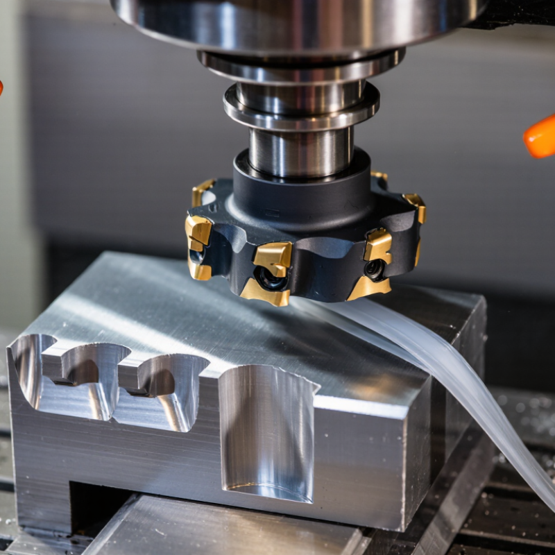
A chamfering cutter is a cutting tool designed to remove a sharp edge from a workpiece. It creates a sloped surface, called a chamfer, instead of leaving a square corner. This small change can improve assembly, safety, and appearance. It can also help screws, pins, or mating parts enter more smoothly.
The cutter usually has angled cutting edges arranged around a central axis. When it rotates, each edge removes a controlled amount of material from the workpiece. Common designs include countersink-style cutters, single-angle cutters, and adjustable tools. The selected angle and diameter depend on the drawing, material, and required edge size. A hardened steel cutter may suit general machining, while carbide tools often handle abrasive materials more effectively.
During use, the machine must hold the cutter and workpiece firmly. Excessive feed pressure can leave chatter marks or a rough, uneven edge. I normally begin with a light pass and inspect the surface under clear lighting. In practice, the first cut is rarely perfect. Tool runout, worn edges, and incorrect speed can change the result. Measuring the chamfer with a gauge or caliper provides better control than judging it by eye. Coolant may reduce heat, but its value depends on the material and cutting conditions. A clean edge matters. Yet a chamfer that is too deep can weaken the part or alter its fit. That detail is easy to miss.
What Is a Chamfering Cutter and How Does It Work?
How Does a Chamfering Cutter Work?
A chamfering cutter removes a sharp corner from a workpiece. Its angled cutting edge creates a sloped surface instead of a square edge. This small change can improve safety, assembly, and appearance. It also reduces burrs around drilled holes and machined edges. The cutter may be used with a manual machine, CNC equipment, or a compatible drilling setup.
The process begins when the spindle rotates the cutter against the material. The angled tip contacts the edge and removes a controlled amount of metal. Feed speed, spindle speed, cutter angle, and cutting depth all affect the result. A shallow pass usually produces a cleaner surface. Excessive pressure can cause chatter, heat, or an uneven chamfer. Keep the workpiece firmly secured.
Before cutting, the operator checks the required chamfer size and selects a matching tool angle. A test cut on scrap material can reveal setup errors. Measure the finished edge with a chamfer gauge or caliper. Even a slight depth mistake may affect part assembly. Cutting fluid can help with some metals, although the correct choice depends on the material and tool geometry. The method sounds simple, but it is not completely forgiving. I would not trust appearance alone; touch, measurement, and repeatability matter.
A chamfering cutter removes material from an edge at a controlled angle. It creates a sloped surface instead of leaving a sharp corner. Machinists use chamfers to improve assembly, reduce burrs, and protect operators from exposed edges. Cutter performance depends on tool geometry, workpiece material, spindle speed, and feed rate.
Single-flute cutters are useful for soft materials and small machines. Their open flute clears chips efficiently. Multi-flute cutters provide smoother cutting and faster production on harder materials. However, excessive flute engagement can trap chips and damage the edge. Solid carbide cutters offer strong wear resistance and precise results during repeated work. Indexable cutters use replaceable inserts, making them practical for larger chamfers and economical maintenance. Countersink-style cutters can create both a chamfer and a screw seat, but their angle must match the fastener.
The cutter angle should match the drawing, not visual guesswork. Common angles include 45 degrees, 60 degrees, and 90 degrees. A 45-degree cutter is often chosen for general edge breaking. Narrow workpieces may need a smaller diameter to prevent vibration. I have found that a sharp cutter can still produce poor results when the workholding is weak. That detail is easy to miss. Check the first part under magnification, measure the chamfer width, and adjust the feed carefully. Scrap can reveal more than assumptions.
A chamfering cutter removes material from an edge at a controlled angle, often 45 degrees. Its cutting edges create a smooth transition for assembly, deburring, or countersink preparation. Material choice strongly affects tool life, heat, and surface quality.
Aluminum is generally easy to chamfer because it cuts cleanly, but it can stick to the tool. The U.S. Geological Survey reported about 70 million metric tons of global primary aluminum production in 2023. Steel and cast iron are also common targets, although hardened steel needs rigid fixturing and slower cutting conditions. Stainless steel requires sharp edges and steady coolant control because it work-hardens quickly. Titanium is machinable, but its low thermal conductivity concentrates heat near the cutting zone. A chamfer may look acceptable while the cutter is already wearing. Plastics and carbon-fiber composites can also be machined, but they need controlled feed rates to prevent melting, fuzzing, or delamination. Industry research from the International Titanium Association highlights titanium’s demanding heat-management requirements during machining.
Tips: Match the cutter material and coating to the workpiece. Use a test cut on the actual batch, not only a handbook value. Check the edge under magnification. Chips tell a story, but not always the whole story. Brass, copper, and soft plastics may need different geometries because sharp edges can grab or smear. Toolpath direction matters too, especially on thin panels. The assumption that one chamfer setting fits every material deserves checking.
| Material or Machining Factor | Can It Be Chamfered? | Recommended Cutter Configuration | How the Cutter Works | Important Considerations |
|---|---|---|---|---|
| Mild and Low-Carbon Steel | Yes | High-speed steel or carbide chamfer mill; coated carbide is suitable for production work. | Angled cutting edges remove material from the part edge to create a controlled bevel, commonly at 45 degrees. | Use sharp edges and adequate chip evacuation to reduce built-up edge and burr formation. |
| Stainless Steel | Yes | Rigid carbide cutter with a positive or application-specific geometry and suitable coating. | The cutter shears the workpiece at an angle while maintaining a defined chamfer width and surface finish. | Avoid dwelling in one location because stainless steel can work-harden. Stable fixturing and coolant may help. |
| Tool Steel and Alloy Steel | Yes, depending on hardness | Carbide for annealed or pre-hardened material; carbide, ceramic, or CBN may be used for hardened steel when application conditions permit. | The cutting edge removes a narrow strip of material from the corner without changing the main part geometry. | Hardness, cutter rigidity, and heat control strongly affect tool life. Use cutting data recommended for the specific tool and hardness. |
| Cast Iron | Yes | Carbide cutter; geometry should match gray, ductile, or other cast-iron grades. | The cutter forms a bevel by controlled peripheral or face milling along the edge. | Cast-iron dust is abrasive. Use effective chip and dust management, and inspect the edge for inclusions or interrupted cuts. |
| Aluminum and Aluminum Alloys | Yes | Sharp, polished carbide cutter with large chip spaces; uncoated or aluminum-focused geometry is commonly used. | High-shear flutes cut the edge cleanly and produce a visible bevel for deburring, assembly, or appearance. | Prevent aluminum from sticking to the cutting edge. Air blast or suitable coolant can improve chip evacuation. |
| Copper, Brass, and Bronze | Yes | Sharp carbide or high-speed steel cutter selected for the particular alloy and its ductility. | The angled edge cuts away the corner while limiting deformation around the chamfer. | Ductile copper may smear if the tool is dull. Maintain a sharp edge and avoid excessive rubbing. |
| Titanium Alloys | Yes, with controlled parameters | Rigid carbide chamfer cutter with appropriate geometry, low runout, and sufficient coolant. | The tool makes a shallow angled cut while minimizing heat concentration and edge rubbing. | Titanium has low thermal conductivity and can generate heat. Use conservative, application-specific cutting conditions. |
| Nickel-Based Superalloys | Yes, but difficult | Rigid carbide tooling with suitable edge preparation; use specialized tooling and parameters for demanding applications. | A controlled feed and engagement allow the angled cutting edge to remove material without excessive rubbing. | These alloys retain strength at high temperature and may work-harden. Minimize vibration and avoid unnecessary pauses. |
| Plastics and Engineering Polymers | Yes | Very sharp high-speed steel or carbide cutter with polished flutes and generous chip clearance. | The cutter slices the edge to create a clean bevel while limiting melting, tearing, or distortion. | Control heat and clamping pressure. The correct cutting speed depends on the polymer’s melting and softening behavior. |
| Carbon Fiber and Glass-Fiber Composites | Yes, with composite-specific tooling | Carbide, diamond-coated, or polycrystalline diamond tooling selected for abrasive fibers and required edge quality. | The cutter removes the edge at a defined angle while reducing fiber pull-out and delamination. | Use dust extraction and sharp tooling. Support the workpiece well and verify the cutter’s suitability for the laminate. |
| Glass, Ceramics, and Carbide | Conditionally | Diamond abrasive tools or specialized grinding processes rather than ordinary metal-cutting chamfer mills. | Material is generally removed by abrasion or grinding, which reduces the risk of fracture compared with a conventional impact cut. | Brittle materials require controlled engagement, rigid support, and appropriate coolant or dust control. |
| Chamfer Angle and Width | Adjustable within the tool design | Fixed-angle, adjustable-angle, countersink-style, or CNC-programmed chamfering cutter. | The tool’s included angle and axial or radial position determine the final bevel angle and chamfer width. | Confirm the drawing tolerance, tool angle, workpiece datum, and machine alignment before production. |
Choosing a chamfering cutter starts with the edge, not the tool catalog. A 45-degree cutter suits many deburring tasks, while 60 or 90 degrees can create a more defined edge. Match the cutter angle to the drawing, hole size, and required finish. For steel, carbide cutters usually handle heat and abrasion well. Aluminum often needs sharper geometry and generous flute space. Coating choice matters, but geometry matters more.
The World Robotics 2024 report recorded 541,302 industrial robot installations worldwide in 2023. Automated cells therefore demand repeatable chamfer sizes and stable tool life. Choose a cutter diameter that reaches the edge without crowding nearby walls. Check the machine’s maximum speed, holder runout, and spindle power. Keep it rigid. Even 0.02 mm of runout can produce an uneven chamfer on a small hole.
Set cutting speed and feed from the cutter maker’s technical data, then reduce them for weak workholding or interrupted cuts. Use a test piece first. Measure the chamfer with a gauge, optical comparator, or calibrated caliper. The 2024 Smart Manufacturing and Operations Survey reported that 86% of manufacturers view smart manufacturing as important for competitiveness, but automation cannot correct poor setup decisions. I still inspect the first five parts. A chart can mislead. Watch for burrs, vibration marks, and a bright rubbed edge; each suggests a different correction. Lowering feed alone may hide the real problem.
CLA-VAL UK Limited
Dainton House
Goods Station Road
Tunbridge Wells
Kent, TN1 2DR
© 2025 CLA-VAL UK | site map | Terms and Conditions of Sale and Warranty | Privacy policy