Pressure Reducing
Pressure Sustaining / Pressure Relief
Flow Control valves
Float Valves - Level Control
Electrically Actuated Valves
Pressure Modulation - Remote Control
Altitude Valves - Level Control
Burst Control Valves
Pump Control
CLA-VAL "HYTROL" Main Valve
Valve Controllers and Data Loggers
Air Valves
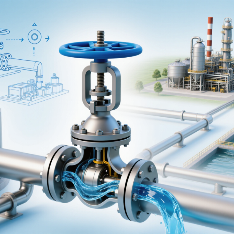
A Level Control Valve protects tanks, pipelines, and process equipment from unstable liquid conditions. It adjusts flow automatically as the measured level changes. That action seems simple. It is not.
The United Nations World Water Development Report 2024 states that agriculture represents approximately 70% of global freshwater withdrawals. This pressure makes accurate water and chemical handling increasingly important. In refineries, food plants, and wastewater facilities, a small level error can cause overflow, pump cavitation, product loss, or an unexpected shutdown. The U.S. Environmental Protection Agency also identifies reliable process control as an important part of effective industrial water management. These findings give level regulation a practical purpose beyond automation.
Greg McMillan, a respected process-control specialist, writes, “The control valve is the most important final control element in a control loop.” His observation explains why valve selection deserves careful engineering. A Level Control Valve must match the fluid, pressure range, temperature, tank geometry, and required response speed. Incorrect sizing can create hunting, noise, erosion, or poor shutoff. The failure may appear elsewhere. The valve may be blamed too quickly.
A dependable design combines accurate instrumentation, suitable valve characteristics, and documented commissioning tests. Operators should inspect actual operating trends, not trust calculations alone. Field conditions often disagree with the original design. That is the uncomfortable lesson. A valve can be technically correct yet perform badly when maintenance, flashing, solids, or changing flow demands are ignored. Understanding these risks clarifies why level control valves remain essential to safe, efficient, and measurable process operation.
A level control valve is an automatic device that maintains liquid height inside a tank, vessel, or process line. It receives a signal from a level sensor or controller. The valve then opens or closes to adjust incoming or outgoing flow. In practice, it acts like a careful gate, not a simple on-and-off switch.
For example, a storage tank may need a steady level while downstream equipment uses fluid continuously. If the level falls, the valve can open further and admit more liquid. If the level rises, it restricts flow. This protects pumps from running dry and reduces overflow risks. Stable levels also support consistent heating, mixing, and residence time. Small changes matter.
The valve usually includes an actuator, control body, and position feedback. Selection depends on fluid properties, pressure, temperature, flow range, and response speed. During field checks, technicians should inspect calibration, impulse lines, seals, and unusual vibration. A well-sized valve can still perform poorly when the sensor is placed badly or the process reacts slowly. That detail is easy to underestimate. It is not magic. Control tuning may need adjustment after installation because real piping rarely behaves exactly like a design model. In my experience, observing the vessel during start-up often reveals issues that calculations miss.
Why Is a Level Control Valve Important?
How Does a Level Control Valve Work?
A level control valve regulates liquid height inside a tank, separator, or process vessel. It works with a level transmitter and a controller. The transmitter measures the liquid level continuously. It may use radar, ultrasonic signals, or differential pressure. The controller compares the measured level with the selected setpoint. If the level rises too high, it signals the valve to open further. More liquid then leaves the vessel. Small changes matter.
The valve actuator receives this control signal and moves the valve stem. An air-operated actuator is common in industrial systems. A positioner helps the valve reach the requested opening accurately. When the level falls, the controller reduces the valve opening. This slows the outlet flow. Correct action depends on the process design. A failed-open or failed-closed position can protect equipment during an air or power loss. Watch the response time.
Real installations are less tidy than diagrams suggest. Foam, turbulence, changing liquid density, and blocked sensing lines can distort the measurement. A valve may then hunt between open and closed positions. That assumption can fail. Technicians should check calibration, impulse lines, actuator pressure, and valve travel during maintenance. I have found that small installation details often affect stability more than expected. A properly tuned loop still needs observation after startup, especially when flow conditions change.
Why Is a Level Control Valve Important?
What Functions Does a Level Control Valve Perform?
A level control valve regulates liquid flow to keep a vessel near its target level. It receives a signal from a float, displacer, or electronic transmitter. The valve then opens or closes according to changing process conditions. Small changes matter.
In practical operation, this valve prevents overflow, protects pumps from running dry, and supports stable production. For example, when a storage tank level drops, the valve can increase inlet flow. When the level rises, it restricts flow or redirects liquid. This response reduces manual intervention and helps operators maintain safer working conditions.
The valve also handles disturbances, such as sudden demand changes or fluctuating inlet pressure. A properly selected actuator can move the valve smoothly, avoiding rapid cycling and unnecessary wear. Fail-open or fail-closed action may provide additional protection during instrument or power failure. The correct choice depends on the process risk.
Reliable performance requires more than installing the valve. Technicians should check calibration, inspect the sensing device, and confirm that the actual level matches the control signal. A valve may appear functional while responding too slowly. That is easy to miss. Poor sizing can also cause hunting, noise, or unstable levels. Field observations should guide adjustments, because real process behavior does not always match design assumptions.
A level control valve is important because it keeps liquid within a safe, usable range. In a storage tank, changing inflow can quickly raise the level. Without accurate control, liquid may overflow, pumps may run dry, or production may stop. The valve adjusts flow as the measured level changes. This protects equipment and supports steady operation.
Good control also improves product quality. A reactor, separator, or cooling vessel often needs a stable liquid volume. Small level changes can affect pressure, temperature, and residence time. During routine inspections, technicians should check the sensor, actuator, valve body, and surrounding pipework. A sticky valve may respond too slowly. A leaking valve may waste energy and create an unnoticed hazard.
The valve is not a complete solution. Poor sensor placement can cause false readings. Incorrect settings can create constant opening and closing. That wear is expensive. Operators should compare instrument readings with the actual tank condition, especially after maintenance. Simple records help identify gradual changes before they become failures. Reliable level control depends on correct sizing, careful commissioning, and regular testing, not the valve alone. Mistakes still happen. The control loop deserves attention.
Why Is a Level Control Valve Important?
How Should a Level Control Valve Be Selected and Maintained?
Selecting a level control valve begins with process facts, not catalog size. Record fluid density, viscosity, temperature, pressure, flow range, and vessel volume. Check both normal and upset conditions. A valve sized only for average flow may hunt, cavitate, or fail to control low levels. IEC 60534-2-1 provides recognized methods for calculating valve capacity and flow coefficients. Use those calculations with verified plant data. Do not trust an old datasheet blindly.
Actuator sizing deserves equal attention. Confirm the required shutoff force, available instrument air, signal type, and failure position. A fail-closed valve may protect against overflow, while fail-open operation may protect cooling or downstream equipment. The decision depends on the process hazard. The U.S. Department of Energy’s Operations & Maintenance Best Practices Guide reports that predictive maintenance can reduce costs by about 8–12% compared with preventive maintenance, and much more compared with reactive work. Inspect valve travel, position feedback, impulse lines, and air quality during planned shutdowns. Look for sticky movement, leaking packing, noisy throttling, or unstable level trends.
Small details matter. Keep spares documented. Record trim material and calibration results. Maintenance teams sometimes replace a valve before checking a plugged sensing line. That mistake is expensive. A clean spreadsheet does not prove reliable control. Recheck assumptions after production changes, because the original service conditions may no longer exist.
| Data Dimension | Engineering Parameter | Typical Data or Selection Guidance | Why It Matters | Maintenance or Verification Action |
|---|---|---|---|---|
| Process Function | Controlled liquid level | Maintain the vessel level within the operating band defined by the process design. The normal operating level should remain between the low-level and high-level alarm limits. | Stable level control helps prevent pump cavitation, vessel overflow, loss of residence time, and exposure of heating or cooling surfaces. | Review operating trends and alarm settings after process changes, trips, or repeated high- and low-level alarms. |
| Valve Location | Inlet or outlet service | For an inlet valve, increasing valve opening normally raises vessel level. For an outlet valve, increasing valve opening normally lowers vessel level. | The controller action and fail position depend on whether the valve adds or removes liquid from the vessel. | Confirm the actual process response during commissioning and after actuator, positioner, or piping work. |
| Flow Capacity | Minimum, normal, and maximum flow | Size the valve using the complete operating range, including start-up, turndown, normal load, maximum load, and upset conditions. Do not size only for the average flow. | A valve that is too small cannot meet peak demand; an oversized valve may operate nearly closed and become difficult to control. | Compare actual valve position with the expected operating range. Persistent operation below approximately 10% or above approximately 90% open may justify a sizing review. |
| Pressure Conditions | Inlet pressure, outlet pressure, and differential pressure | Use the minimum and maximum upstream and downstream pressures at the valve. Calculate capacity with the applicable liquid or gas valve-sizing method. | Valve capacity, noise, cavitation risk, and actuator force are strongly affected by pressure drop. | Verify pressure transmitters and compare measured pressure drop with the original design basis. |
| Liquid Properties | Density, viscosity, temperature, vapor pressure, and solids | Use values at the actual operating temperature. Record viscosity in cP, density or specific gravity, vapor pressure, corrosiveness, and suspended-solids content. | These properties influence flow capacity, trim selection, erosion, plugging, flashing, and cavitation. | Update the valve datasheet when the fluid composition, temperature, or concentration changes. |
| Valve Characteristic | Inherent flow characteristic | Equal-percentage trim is commonly considered for wide load variation and pressure-dependent processes. Linear trim may be suitable where process gain is relatively constant. | The characteristic affects loop gain and helps determine whether the controller can maintain a stable level across the operating range. | Check for excessive cycling, sluggish response, or large gain changes as load changes; retune only after mechanical issues are excluded. |
| Valve Authority | Valve pressure-drop ratio | As a preliminary design target, the valve should provide a meaningful portion of the available system pressure drop at normal flow. The exact target depends on the piping system and process. | Very low authority can make the valve sensitive to system-pressure changes and can reduce controllability. | Recalculate authority if pumps, piping, heat exchangers, or operating pressures are changed. |
| Cavitation and Flashing | Vapor-pressure-related damage | Compare local pressure inside the valve with the liquid vapor pressure. If pressure falls below vapor pressure and does not recover, flashing may occur; if bubbles collapse downstream, cavitation may occur. | Cavitation can cause noise, vibration, trim damage, and shortened valve life. | Inspect for pitting, abnormal noise, vibration, and unstable flow. Consider multistage pressure reduction or anti-cavitation trim when required by the calculation. |
| Valve Body and Trim | Materials and pressure-temperature rating | Select materials compatible with the fluid, temperature, pressure, corrosion environment, and erosion risk. Confirm that the pressure-temperature rating meets the piping design conditions. | Material incompatibility can cause corrosion, leakage, contamination, or sudden loss of containment. | Inspect body, bonnet, packing area, bolting, and trim for corrosion, erosion, galling, and leakage. |
| Actuator Sizing | Required thrust or torque | Size the actuator for maximum differential pressure, friction, packing load, shutoff requirement, and a suitable design margin. Account for the available instrument-air or electrical supply. | Insufficient actuator capacity can cause position loss, poor shutoff, or failure to move during an upset. | Verify full-stroke travel, supply pressure, spring condition, and the actuator’s fail action during planned maintenance. |
| Fail-Safe Position | Fail-open, fail-closed, or fail-in-place | Choose the position that places the vessel and connected equipment in the safer condition after loss of air, power, or control signal. The correct choice is process-specific. | Fail action is a key layer of protection against overflow, dry running, overheating, or loss of cooling. | Test the fail position under a controlled procedure and document the result after actuator or control-system work. |
| Control Signal | Controller output and feedback | Common analog instrumentation uses a 4–20 mA signal, where 4 mA and 20 mA represent the configured measurement range. Digital communication may also be used. | Correct signal scaling prevents incorrect valve movement and misleading level indications. | Check signal range, calibration, wiring polarity, feedback accuracy, and alarm settings. |
| Installation | Flow direction and piping arrangement | Install the valve according to the flow arrow and manufacturer’s technical requirements. Provide adequate pipe support, access, isolation, and safe drainage where needed. | Incorrect orientation or pipe strain can increase wear, leakage, vibration, and maintenance difficulty. | Inspect supports, flanges, gaskets, isolation valves, drains, and access clearances during field checks. |
| Commissioning | Stroke and loop test | Confirm 0–100% commanded travel, correct feedback, correct controller action, proper signal scaling, and stable response at representative operating conditions. | Functional testing detects reversed action, calibration errors, stiction, deadband, and incorrect fail behavior before normal operation. | Record as-found and as-left results, travel curves, alarm checks, and any controller tuning changes. |
| Routine Inspection | External condition and leakage | Inspect for packing leakage, flange leakage, abnormal noise, vibration, corrosion, loose hardware, damaged tubing, and positioner faults. | Early detection reduces the likelihood of unplanned shutdowns and secondary equipment damage. | Perform visual and operational checks at an interval based on service severity, operating history, and site procedures. |
| Calibration | Level transmitter and valve positioner | Use the site’s instrument calibration procedure and applicable accuracy requirements. Calibration intervals should be based on criticality, drift history, and regulatory requirements. | A control valve cannot maintain the correct level if the transmitter or position feedback is inaccurate. | Compare reference readings with instrument output and document calibration drift and corrective action. |
| Performance Indicator | Valve travel, cycling, and process deviation | Trend valve position, level deviation, controller output, alarm frequency, and cycle rate. There is no universal acceptable cycle rate; persistent rapid cycling requires investigation. | Frequent cycling may indicate poor tuning, excessive deadband, stiction, inadequate valve authority, or an unstable process. | Inspect the valve and actuator before changing controller tuning. Use trend data to distinguish mechanical and control-system problems. |
| Maintenance Interval | Preventive maintenance planning | Use a risk- and condition-based interval. | Service severity varies widely with pressure, temperature, corrosiveness, solids, cycling, and safety criticality, so a single universal interval is not technically reliable. | Establish an initial inspection interval from operating history and site procedures, then shorten or extend it using documented condition data and failure history. |
| Documentation | Valve datasheet and maintenance record | Maintain the tag number, service, size, rating, materials, flow coefficients, pressure conditions, actuator data, fail action, calibration results, and repair history. | Complete records support correct replacement, troubleshooting, audits, and future sizing decisions. | Update the record after every inspection, calibration, trim replacement, actuator change, or process modification. |
CLA-VAL UK Limited
Dainton House
Goods Station Road
Tunbridge Wells
Kent, TN1 2DR
© 2025 CLA-VAL UK | site map | Terms and Conditions of Sale and Warranty | Privacy policy